We at Coppell TV Repair do our best to protect ourselves and our customers from bad parts, but ultimately nobody would take care of the customer than the customer himself.
Of course by publishing such information we inevitably also continue to indicate our competitors some of which we are proud to see as subscribed followers of our blog.
For what it's worth, that's the nature of this business.
Competitors, feel free to copy this and post it on your sites...you are going to do it anyway, you might as well do it with our blessing.
Now back to the task at hand.
The tests described below are applicable with the IC on and off board. Of course we strongly recommend that you apply them before you solder any IC on the board - you'll save time and you'll also increase the odds of being able to return the IC back to the vendor with least worries.
Those tests are not complete in a sense that they do not guarantee that the IC will work properly.
But they clearly indicate if it is bad and while it's not guaranteed, we find that 99.9% of the time when an IC passes them it works good on a board.
It all boils down to detecting continuity (shorts) or low resistance (ohms) between certain pairs of pins on the module..
If you find one the STK795-518 is certainly bad.
The tests can be done with the IPM on or off the board.
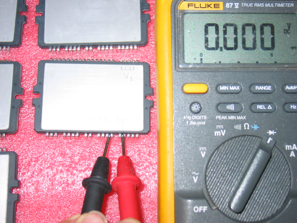
Here's a picture of the pins of interest:

Here's the simple rule:
THERE MUST BE NO CONTINUITY (SHORT) BETWEEN ANY COMBINATION OF THOSE!
IF YOU FIND A SHORT THEN YOUR STK795-518 IS DEFECTIVE.
This is actually 100% correct for all other plasma IPM modules.
There are 4 inputs/outputs which result in 6 possible tests (Vs-GND, Vs-SUSout, Vs-ERout, GND-SUSout, GND-ERout, SUSout-ERout), but in reality two are the most common failures that we see in STK795-518:
1) Vs shorted to one of the two sustain outputs:
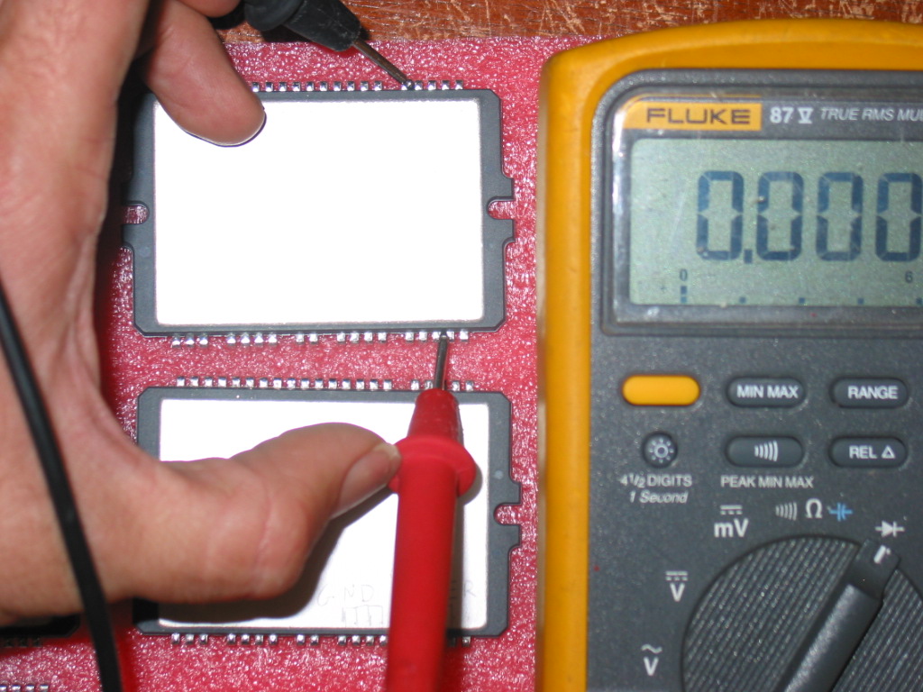
2) The other sustain output shorted to ground: